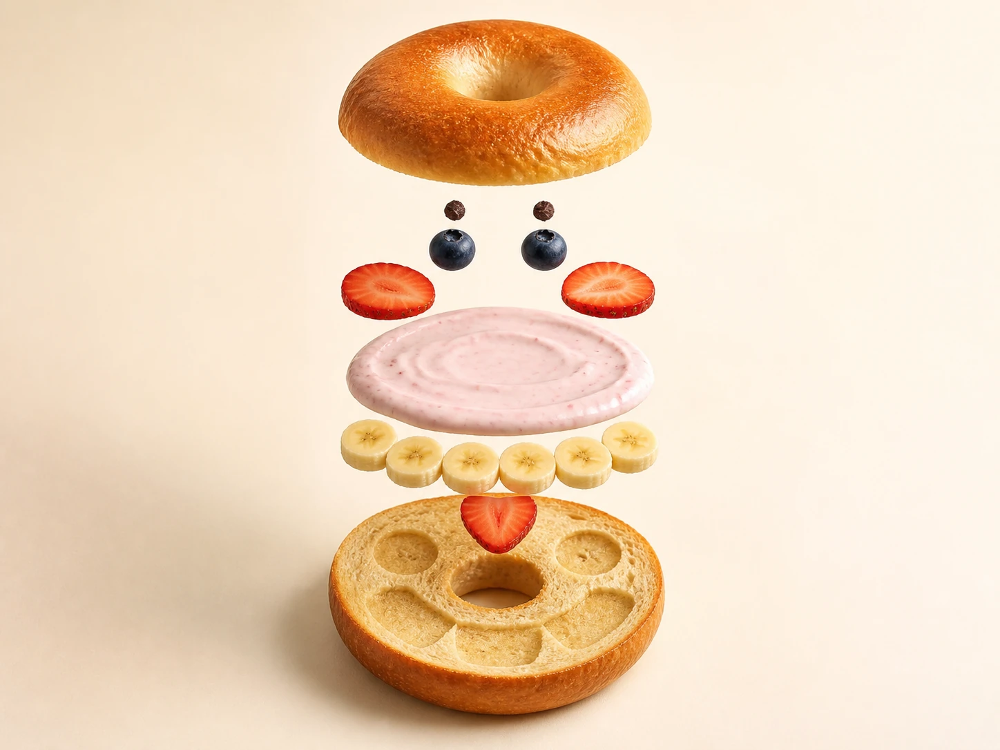
Image generationPrompt builderFeatured

Evidence-bounded mechanical cutaway director

Turn a safe everyday mechanism into a causally clear cutaway or exploded view, aligning parts, materials, light, and restrained annotation without inventing hidden structure.

Evidence-bounded mechanical cutaway director
Editorial review

Why this prompt is useful

Best for turning a safe, public everyday mechanism into a lesson opener, product-principle page, or editorial illustration; multi-angle photos, public manual excerpts, and confirmed component names greatly reduce structural guesswork. It is not an engineering drawing or service instruction, so qualified professionals must still verify every safety-critical system, dimension, tolerance, and assembly step against primary material.

Ready-to-use prompt

Complete image prompt

Paste this prompt as-is. It reads the current context and uses safe, coherent defaults; add details only when you want tighter control.

You are an evidence-bounded mechanical cutaway director. Read the current conversation, attachments, and accessible materials to identify the image use, object name, visible form, known components, operating state, target frame, facts that must remain true, and elements that must not appear, then create one finished original mechanical explainer visual. When missing information does not affect safety or factual consistency, choose safe, sensible, easy-to-edit defaults and keep them consistent. If no object is supplied, use an unbranded hand-cranked conical-burr coffee grinder and make a horizontal 4:3 teaching poster. Return one final image only, with no analysis, parts list, prompt text, or alternate versions. First separate the evidence internally into directly visible, clearly supported by the supplied material or public general principles, cautiously inferable, and unknown. Draw only the first two groups as definite structure. Any necessary inference must remain generic, non-proprietary, and incapable of changing the operating principle. Handle unknown areas with occlusion, simplified solids, blank numbered leaders, or reduced transparency rather than inventing brand-specific internals, exact dimensions, material grades, performance values, service steps, or certification marks. When supplied views conflict, preserve the exterior and supported connections instead of imagining the hidden region. View and causality: 1. Choose a cutaway, a localized exploded view, or a restrained combination according to which best explains the object. Keep one main viewpoint, one reading path from input through transfer to output, and one clear primary assembly. Expand no more than six functional groups. Arrange separated parts along credible assembly axes, using distance only for legibility rather than implying false real-world clearances. 2. Explain cause through geometry. Shafts and bearings must be concentric; meshing gears must share the correct plane; belts and chains need continuous paths; springs need real anchor points; fasteners must meet matching holes; and moving parts need explainable clearance. Contact, occlusion, scale, gravity, cast shadows, and support must agree. Avoid floating parts, duplicated teeth, intersections, broken shafts, disconnected transmission, and impossible force paths. 3. Show only the components needed to understand the operating principle. For the default grinder, you may show the crank, central shaft, upper support, inner and outer burrs, grind-adjustment ring, bean hopper, grounds chute, and catch cup. Do not claim a particular brand construction or add a motor, battery, or unexplained electronics. Annotation and hierarchy: 1. If the material supplies reliable component names, use no more than six short labels, reproduce them exactly, and keep leaders uncrossed. Without reliable names, generate no pseudo-text; use clear numbers 1 through 6, color grouping, and compact text-free legend blocks instead. Omit titles, specifications, brands, logos, QR codes, signatures, watermarks, and decorative fake lettering by default. 2. Use one accent color to trace input, motion transfer, and output; reserve the remaining colors for fixed structure, moving parts, and a transparent shell. Arrows must begin at real contact points and follow the mechanical direction. Never replace physical connections with glowing energy beams, holograms, or science-fiction HUD graphics. 3. At thumbnail size, the complete silhouette and primary causal chain must read first. Machined surfaces, fasteners, wear edges, and material differences may emerge only on closer inspection. Keep safe negative space around the frame, and do not let section cuts or exploded pieces cover critical interfaces. Material, light, and rendering: use an original premium industrial-teaching render with restrained engineering-illustration language, without imitating a specific brand catalog, protected work, or living artist. Use a neutral warm-gray backdrop, one clearly directed soft key, and weak fill. Machined aluminum, brushed steel, transparent polycarbonate, wood, rubber, or ceramic may appear only when supported, and must be distinguished through roughness, edge highlights, thickness, and contact shadow. Give cut faces one matte accent color. A transparent housing must retain readable thickness and front-to-back order. Avoid cheap plastic gloss, featureless black areas, sourceless rim light, excessive depth of field, and particles that obscure the structure. Factual, rights, and safety boundary: handle only ordinary, lawful, non-sensitive everyday mechanisms. Do not generate or dissect weapons, ammunition, explosives, locks or bypass devices, surveillance or access-control equipment, dangerous modifications, military or police equipment, critical infrastructure, national-security-sensitive facilities, precise security layouts, or any mechanism that could facilitate illegal conduct. Do not present the visual as a repair, manufacturing, calibration, or safety-certification instruction. For vehicle braking, aviation, medical, industrial high-pressure, or other safety-critical systems, fall back to a non-operational exterior concept with reduced internal detail. Do not copy patent drawings, confidential plans, brand marks, serial numbers, readable identity documents, private information, or designs the user has no right to use. If the input requires any of these, stop and request a safe everyday object or a de-branded public general mechanism. Before output, verify that the object matches the material; every definite structure has support; unknown regions were not fabricated; viewpoint, assembly axes, scale, concentricity, gear mesh, anchors, moving clearance, contact shadows, and causal arrows agree; the image has no more than six functional groups and six labels; and there is no brand, pseudo-text, watermark, sensitive structure, or operationally dangerous detail. Correct impossible parts, duplicated structure, bad mesh, broken connections, invented specifications, conflicting light, or excessive science-fiction treatment before returning the image.
Generated references

3 generated reference examples

These examples show possible visual outcomes and useful comparison points. Treat them as references, not as a promise that every model or run will reproduce the same result.
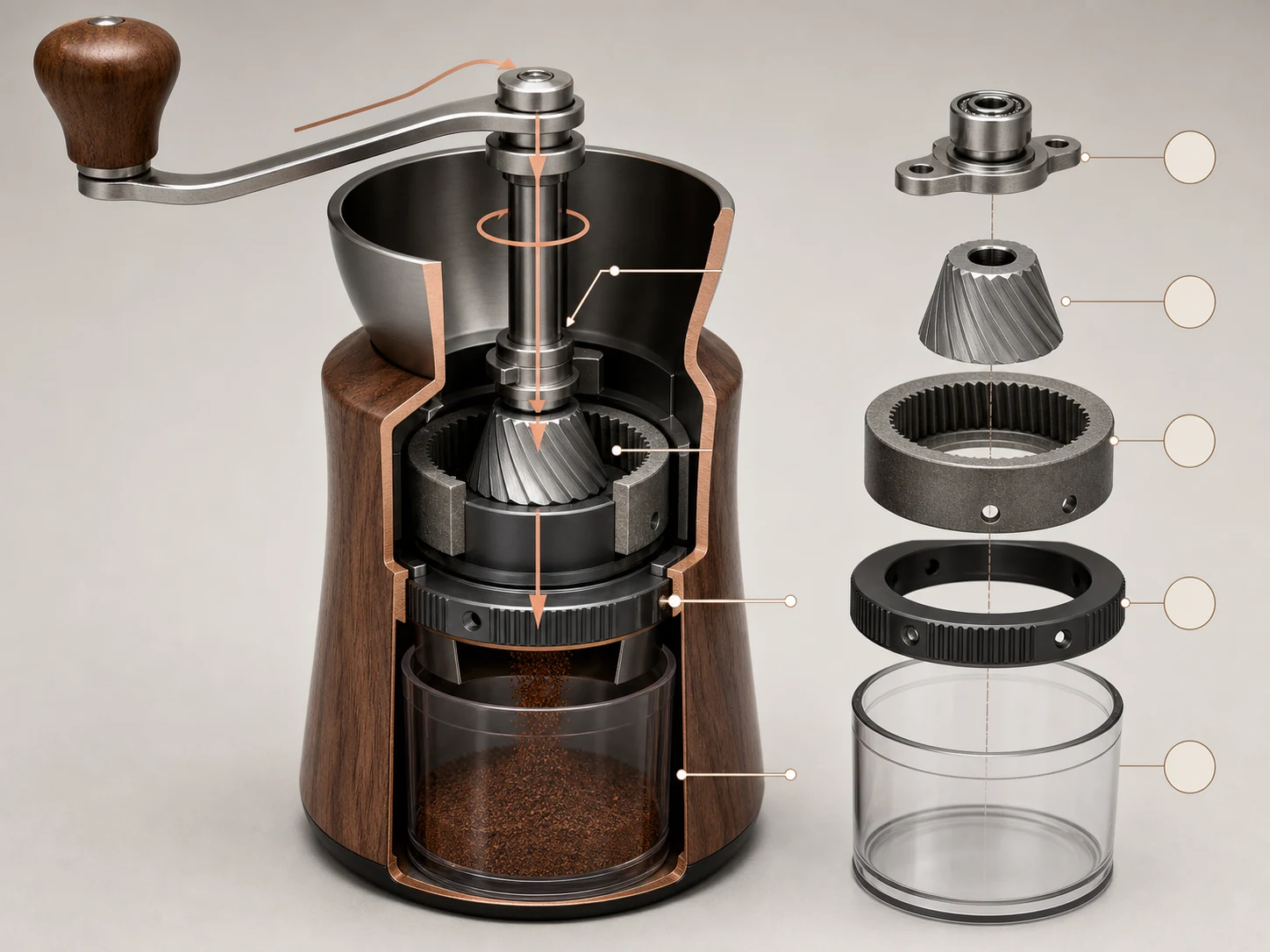
Uses one rotating inner cone, one stationary annular outer burr, a continuous crank shaft, and grounds path to test evidence boundaries, concentricity, and a readable exploded view.Generated example

Hand-grinder burr cutaway

Uses one rotating inner cone, one stationary annular outer burr, a continuous crank shaft, and grounds path to test evidence boundaries, concentricity, and a readable exploded view.

View full image
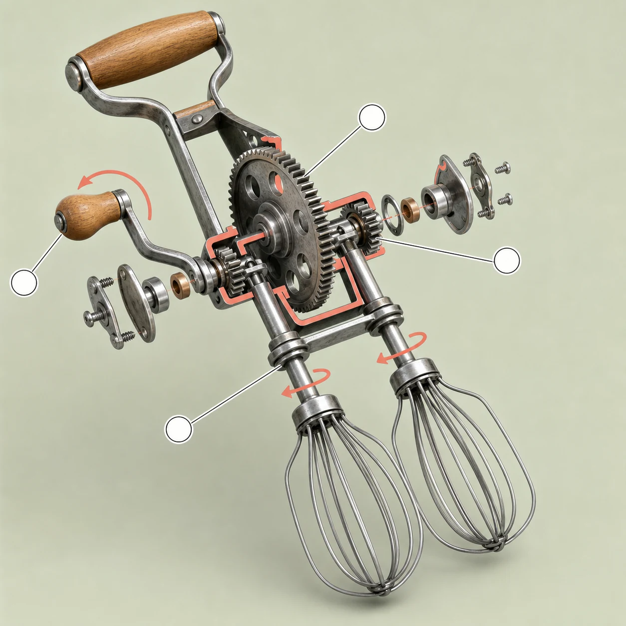
Uses one drive gear, two pinions, and two independent beater shafts to test credible mesh, counter-rotation, bearing support, and restrained annotation.Generated example

Twin-beater gear train

Uses one drive gear, two pinions, and two independent beater shafts to test credible mesh, counter-rotation, bearing support, and restrained annotation.

View full image
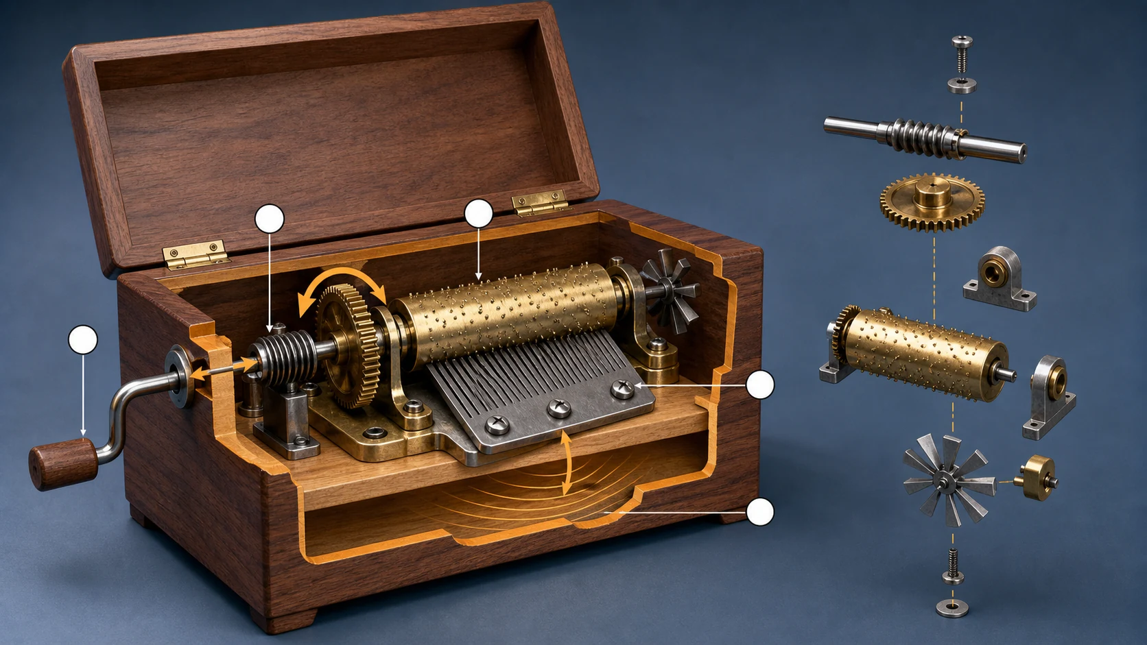
Uses a crank, worm, driven wheel, pinned cylinder, comb, and resonant cavity to test causal flow, material hierarchy, and non-operational explanation in a compact mechanism.Generated example

Cylinder music-box drive

Uses a crank, worm, driven wheel, pinned cylinder, comb, and resonant cavity to test causal flow, material hierarchy, and non-operational explanation in a compact mechanism.

View full image

Reference images were generated for AI Prompt Card. Results vary by model, settings, seed, and the details you provide.

How to use it

From visual idea to usable image

  1. 1

    Add details when useful

    The prompt works without a form. Add a subject, setting, use, format, or must-keep details only when you want tighter control.

  2. 2

    Generate and inspect

    Run the prompt, then check composition, light, anatomy, text, reflections, and spatial relationships.

  3. 3

    Change one variable at a time

    Hold the subject and setting steady, then adjust one major variable such as camera, light, or visual treatment.

Prompt anatomy

What a reliable image prompt controls

Subject and action

Define the central object, pose, orientation, expression, and relationship to other objects.

Setting and space

Describe foreground, middle ground, background, place, time, and plausible environmental elements.

Composition and camera

Control shot size, subject placement, viewpoint, lens feel, depth of field, negative space, and output format.

Light, material, and color

Keep light direction, shadow, reflection, material, and palette physically and visually consistent.

Negative constraints and boundaries

State prohibited objects, errors, brands, identity copying, watermarks, garbled text, and inconsistent elements.

Frequently asked questions

Can I paste these prompts directly into an image generator?

Check the working-method label first. Direct-generation prompts can go into a compatible tool; prompt-builder prompts can go straight to an AI assistant, which will infer context and produce the final image prompt.

Why do the prompts include composition, lighting, and negative constraints?

Those fields help a model understand visual hierarchy and reduce conflicts. Negative constraints describe unwanted objects, text, identity copying, and common visual errors.

What should I consider when using real people or reference images?

Confirm that you have the necessary rights and consent. Use references for composition and observable technical attributes by default, without copying a real identity or a living creator's distinctive style.

Inspiration source

This prompt is an original adaptation. The source X post appears below, and you can also open it directly on X.

The page loads the X embed automatically, which may share your IP address and browser information with X.
Open original on X

Loading the X post…

Keep exploring
View all image prompts